This article provides images and descriptions for the primary MRI scanner components. Every component within an MRI scanner serves a unique purpose, contributing indispensably to the intricate imaging process. From the magnet’s powerful magnetic field to the software’s algorithmic prowess, each element plays a vital role in capturing detailed anatomical images. Moreover, the variations in design directly impact the scanner’s imaging capabilities, dictating factors like scan resolution, sensitivity, and imaging versatility.
- MRI Scanner Components and Functions
- 1. MRI Magnet
- 2. Cryogenic Cooling Systems
- 3. Gradient Coil
- 4. RF Coil
- 5. MRI Coils
- 6. Patient Table
- 7. Operator Console
- 8. PDU (Power Distribution Unit)
- 9. Gradient Amplifiers
- 10. RF Amplifier
- 11. RF Receiver Assembly
- 12. Image Reconstruction Computer
- 13. Peripheral Devices
- 14. MRI Patient Safety Systems
- 15. RF Shielding
- 16. Faraday Cage
- Overview
MRI Scanner Components and Functions
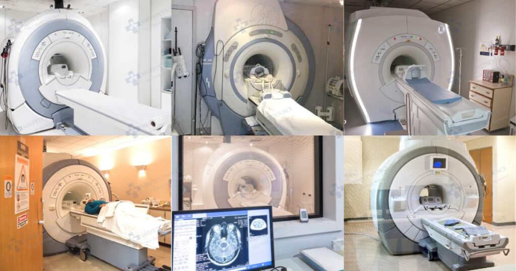
1. MRI Magnet
At the heart of an MRI scanner lies a powerful magnet, generating a strong magnetic field. This magnetic field aligns the protons in the patient’s body, crucial for signal generation during imaging. MRI magnets vary in strength, with higher-field magnets offering greater image resolution but often requiring higher capacity cooling systems.
Related Article: MRI Superconductive Magnet Explained
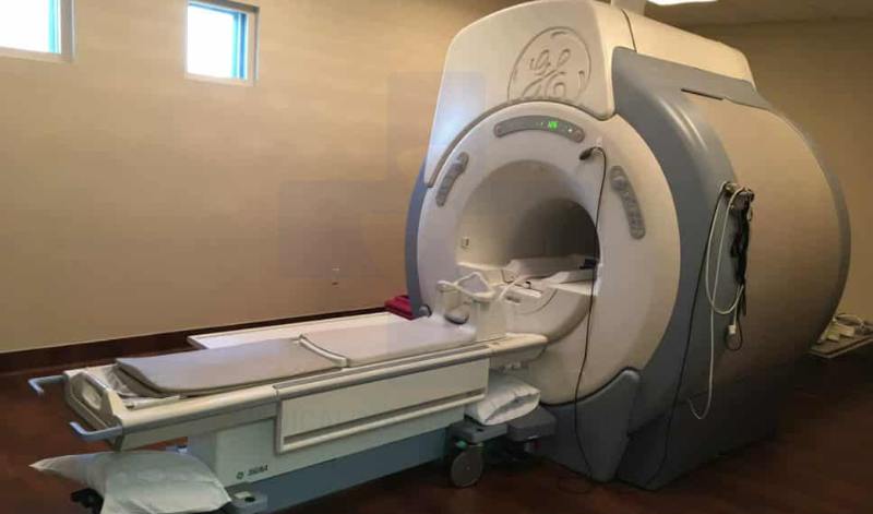
MRI scanner bore
Refers to the tunnel where the patient moves in and out of the MRI magnet. At the very center of the MRI scanner bore is the MRI isocenter. This is where the MRI magic happens.
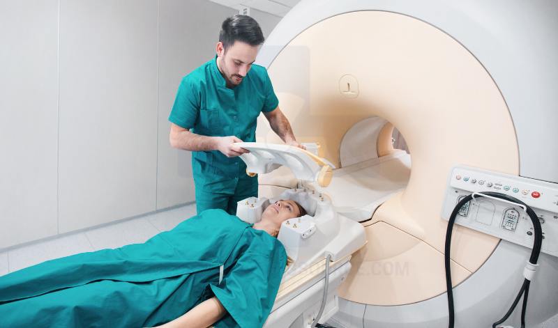
Patient landmark laser
A system of precisely aligned lasers used to accurately position the patient on the MRI table. The laser crosshair assembly aligns anatomical landmarks with the magnet isocenter. It ensures patients are at the correct imaging plane and provides repeatable scan accuracy.
MRI cryostat
An insulated container within the MRI magnet vessel that keeps the MRI magnetic field coils extremely cold.
Magnet vacuum vessel
The vacuum vessel prevents heat from reaching the cold magnet cryostat by removing nearly every air molecule within the space. Without molecules to radiate heat into or out of the cryostat, the vacuum around an MRI cryostat acts as a thermal shield. It functions similar to the insulated containers that help keep your coffee hot without burning your hands.
Liquid Helium
While this may not exactly be an MRI scanner component, it is an essential part of an MRI scanner. The liquid helium cools the superconducting coils down to around 4 kelvin in order to maintain superconductivity in the Niobium Titanium coils.
Superconducting Coils
The MRI main superconducting coils carry large currents with no electrical resistance to generate a stable magnetic field that is always on. The main MRI magnet coil windings are made of a niobium titanium alloy filament embedded in a copper core. The wire is only about 1 millimeter in diameter and each MRI magnet requires between 5,000 and 8,000 windings depending on the magnetic field strength required.
Shim Coils
Also known as supercon shim coils, a series of offset magnetic field coils that allow technologists to make small adjustments that keep the magnetic field uniform.
MRI passive shims
Fixed metal pieces that are basically little strips of small magnetic metal with tape on the back. Using a specialized camera that sees the magnetic field and the MRI software, engineers calculate precisely where to lay small strips of metal inside the MRI magnet bore to help smooth the magnetic field.
Fringe Field Shielding Coils
Also referred to as active shielding coils, it consists of a counterwound coil assembly that surrounds the main magnetic field coils to limit how far the magnetic field extends.
Quench Turret
A 10 in diameter port that directs helium gas safely out of the building during an MRI quench. The quench turret is sealed by a burst disk, rated to 10 psi and pressure relief valves that begin venting at about 5 psi to prevent dangerous pressure buildup.
Quench protection circuitry
Circuit of resistors that safely release the over 1.2 Megajoules of stored energy if the MRI magnet quenches.
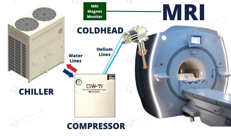
2. Cryogenic Cooling Systems
MRI scanners use cryogenic systems to cool superconducting magnets to very low temperatures, maintaining their superconducting state and maximizing magnetic field stability. The MRI cryogenic cooling system consist of a coldhead, compressor, high pressure helium lines, and magnet monitoring units. These systems regulate temperatures as low as 4 Kelvin (-269C) for optimal operation, dissipating heat to maintain superconductivity.

MRI Coldhead
A crycooler that refrigerates helium. It removes excess heat from the cryostat, and recondenses liquid helium to minimize boil-off. The cold end of the cryocooler is often called the coldhead or cold finger. The coldhead mounts to the coldhead slot on the MRI magnet frame and is thermally coupled to the cryostat with 99.99% pure indium gaskets.
The coldhead and compressor assemblies can be heard in the background of every MRI scan. It is one of the three main MRI scan components responsible for producing the different MRI scan sounds.
Coldhead Port
A vacuum-sealed port where the coldhead mounts and connects to the cryostat.
High-pressure helium lines
Every MRI coldhead requires two high pressure vacuum-jacketed helium gas lines that connect to a helium compressor. One helium line functions as the helium supply and it feeds high pressure helium gas into the coldhead at around 330 psi, after expansion in the coldhead chamber, the helium gas returns from the coldhead to the helium compressor via the “return” line at about 180 psi.
Helium Compressor
Supplies 99.99% pure Helium gas to the cryogen cooler. Also filters contaminants that may be present in the helium gas return line via the coldhead absorber.
Water Chiller
The water chiller circulates cooled water to the MRI system to remove heat from key subunits, including the liquid helium compressor, gradient amplifiers, and other heat-generating components.
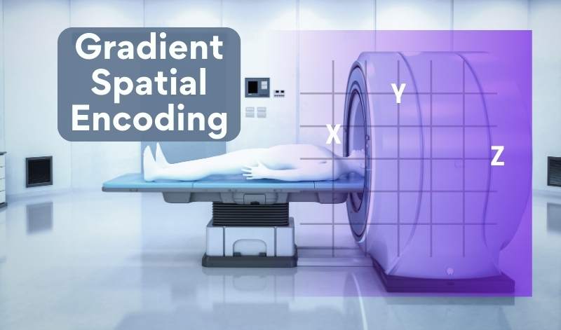
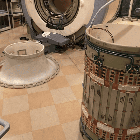
3. Gradient Coil
MRI gradient coils produce varying magnetic fields that enable spatial encoding. These gradients facilitate spatial encoding, allowing for the localization of signals from specific regions within the body. Gradient coil designs may differ based on the strength and configuration required for specific imaging sequences, such as echo-planar imaging or diffusion-weighted imaging.
It creates small changes in the magnetic field for spatial encoding: One gradient coil contains at least one X gradient coil set, a Y gradient coil set, and a Z gradient coil set.

X gradient coil
Located within the gradient coil assembly, the X gradient coil uses saddle-shaped windings positioned on the left and right sides of the imaging volume. Each gradient coil plane is driven by its own dedicated gradient amplifier, which rapidly switches currents, often reaching hundreds of amps, multiple times per second. This rapid, high-current switching creates precise spatial variations in the magnetic field, allowing the X gradient coil to encode image information along the left–right plane of the patient.
Y gradient coil
Encodes magnetic field for the top-bottom plane. The Y gradient coil set uses a saddle style winding placed at the top and bottom of the imaging volume to influence the magnetic field in the y-plane.
Z gradient coil
The Z gradient coil set encodes imaging data in the in-out plane. Unlike the X and Y gradient coils that use a saddle style coil winding, the Z gradients use a Maxwell style coils configuration with two large coils on opposite ends of the imaging volume, or a tightly wound spiral design that runs along the main axis of the MRI magnetic field.
4. RF Coil
The RF coil transmits radio waves and sits within the gradient coil. It is an essential MRI component that is responsible for excitation and detection of imaging signals. RF coils manipulate and detect proton spin states by emitting customized high frequency RF pulses and then capturing the resulting signal changes. Interestingly, RF coils can be tailored to optimize signal reception from specific regions of the body, enhancing image quality and diagnostic accuracy.

RF coil designs vary in shape, size, and configuration depending on MRI scanner models. They are tailored to optimize signal reception and sensitivity for different anatomical regions and imaging protocols within the magnetic field. The RF coil sends radio waves into the body via a built-in receiver coil, known as the body coil.
5. MRI Coils
Anatomically tailored MRI coils significantly boost imaging signals within specific body regions of interest, wrapping snugly around the targeted anatomy. These specialized devices house sets of coils and other electronics, amplifying RF transmit and receive capabilities for optimal image quality.

The term “MRI coil” encompasses various specialized coils for distinct body regions, including knee, neurovascular, spine, and torso array coils. Furthermore, MRI utilizes multiple receiver channels to further augment signal detection and refine image resolution.
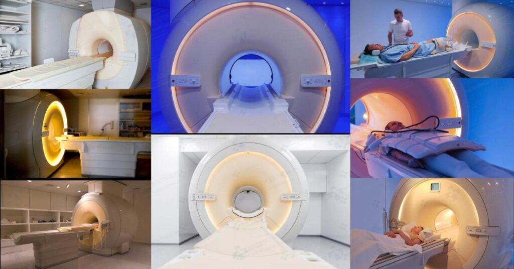
6. Patient Table
The MRI patient table is a movable platform that supports the patient during an MRI scan. It features a cradle that slides into the magnet bore, adjustable height for patient ease of access, and the ability to function as a transport table when disconnected from the magnet docking unit.
The MRI patient table is comprised of an upper and lower assembly. The upper assembly, where the patient lies, includes a tabletop, cradle assembly, and sensors to synchronize table movement during the MRI scan sequence. It moves in and out of the magnet as needed. The lower assembly incorporates elevation controls and can be adapted for use as a portable patient transport or a stationary fixed patient table assembly.

The patient table is precisely calibrated to within 0.5 mm to facilitate accurate imaging. It accommodates MRI-safe padding to comfort for individuals undergoing MRI scans. Patients lie on the table, which moves into the scanner bore for imaging while ensuring stability and safety. Patient tables may feature adjustable height, padding for comfort, and compatibility with specialized coils or accessories for imaging various body parts.
Cradle
The top of the patient table where the patient lies. It is a precisely calibrated support platform that slides the patient into and out of the magnet bore to the magnet isocenter. It is calibrated to within tenths of a millimeter and allows for accurate positioning and controlled movement as required for each scan sequence.
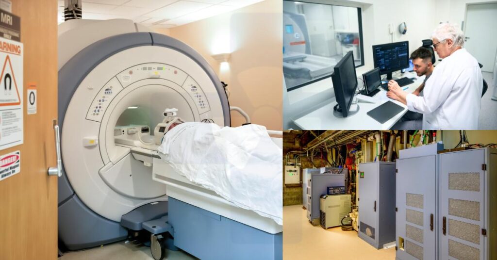
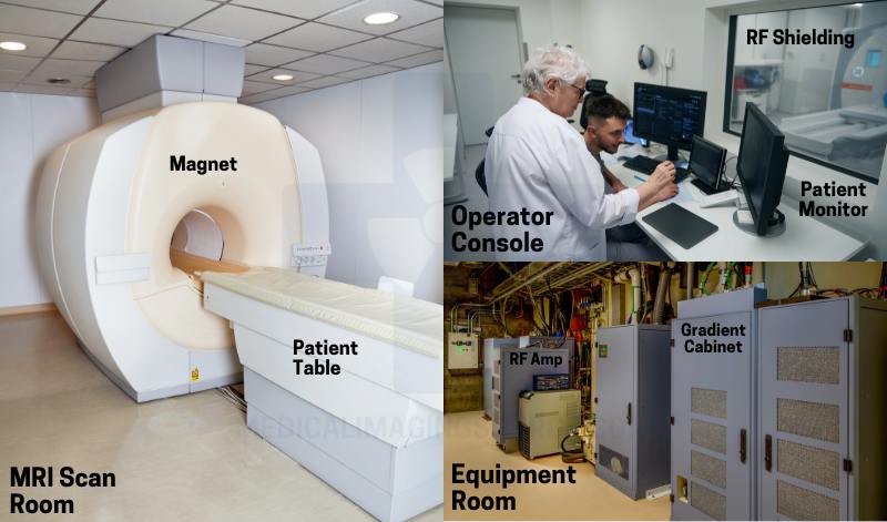
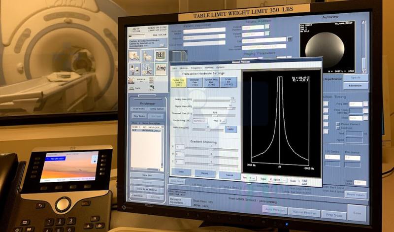
7. Operator Console
The operator console is the primary workstation from which the MRI technologist controls the scan, adjusts imaging parameters, monitors patient status, and reviews images in real time. It integrates the MRI system software interface, which provides a centralized platform for system operation, patient workflow management, and communication with each of the MRI scanner components.
The console functions as the MRI system’s central control hub, facilitating scan parameter adjustment and data acquisition. MRI technologists utilize the console to configure scan protocols, monitor scanner performance, and initiate imaging sequences. Console designs may vary in terms of user interface layout, touchscreen capabilities, and integration of advanced software features for image processing and analysis.
The operator interface streamlines scanner control and monitoring tasks for technologists, allowing them to adjust settings, monitor scans, and troubleshoot operational issues. Operator interfaces may vary in terms of graphical user interface (GUI) design, touchscreen capabilities, and integration with remote access and diagnostic reporting systems.
Image reconstruction computer
The image reconstruction computer processes the raw MR signals received from the receiver board and converts them into the final diagnostic images. Besides the main operator console workstation, the image reconstruction engine is one of the most processing-intensive components of the MRI system. In many older and some modern systems, the image reconstruction engine exists as a standalone system in the equipment room, while in many newer MRI systems, its functionality is often integrated into the operator console for streamlined workflow. This subsystem applies complex and often proprietary image reconstruction algorithms to large imaging volume data sets to produce the final diagnostic quality renderings.
MRI Software
The software interface provides the operator with control over the MRI system, including MRI scan parameter selection, patient positioning guidance, and image acquisition management. It is typically integrated into the operator console workstation, allowing seamless interaction with the scanner, real-time monitoring, and access to reconstruction and post-processing tools.
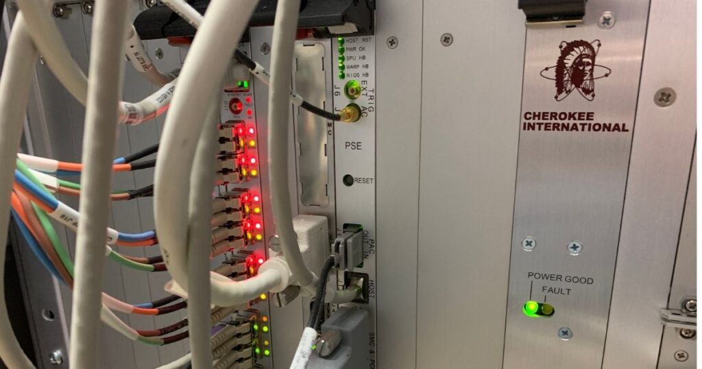
8. PDU (Power Distribution Unit)
Providing electricity to the scanner, the power supply ensures uninterrupted operation during scans. The power supply provides electricity to the MRI scanner, enabling its operation. Stable power delivery is essential for powering magnet coils, gradient amplifiers, RF components, and other subsystems. Power supply designs may vary in voltage regulation, redundancy features, and integration with emergency backup systems to ensure uninterrupted scanner operation.
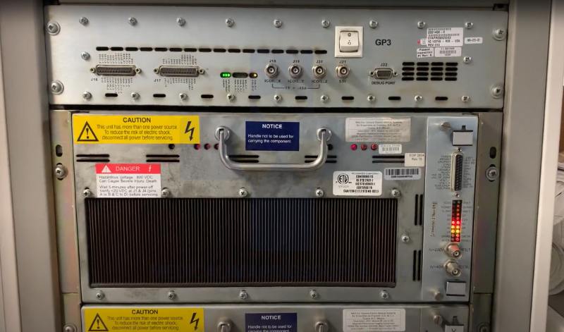
9. Gradient Amplifiers
Gradient amplifiers precisely regulate the strength of gradient coils, enabling accurate spatial encoding during MRI scan sequences. This control ensures high-resolution spatial localization of MR signals. Gradients induce spatial variations in the magnetic field, facilitating precise signal localization within the patient’s body.
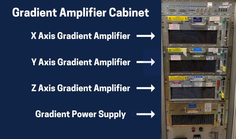
Different gradient designs offer options for various imaging resolutions and sequence requirements, with variations in coil geometry, wire configuration, and gradient strength.
The gradient amplifier drives the MRI’s gradient coils by delivering precise, time-varying currents, controlling the spatial variation of the magnetic field to encode position information of each molecule, and synchronizing system timing with the RF pulses to produce accurate image slices.
10. RF Amplifier
High-power RF amplifiers enhance the power of radiofrequency pulses, optimizing signal transmission and reception efficiency. They guarantee sufficient signal strength for the excitation and detection of MR signals, thereby enhancing signal-to-noise ratio and imaging sensitivity. RF power amplifiers vary in output power, bandwidth, linearity, and distortion characteristics to accommodate specific RF coil designs and imaging protocols.
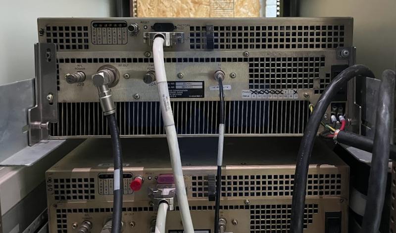
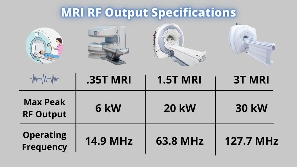
The RF amplifier boosts radio frequency pulses generated by the exciter board. It takes the low-voltage pulses from the exciter board and increases them to the high-power levels needed to excite the MRI’s RF coils. The RF amplifier takes a 3 to 5 volt RF signal and boosts it to levels up to 20 kW in 1.5 T MRI systems and up to 35 kW in 3T MRI systems.
11. RF Receiver Assembly
The RF receiver captures signals emitted by the patient’s body during MRI scans, converting them into digital data for processing. It facilitates signal processing and image reconstruction with high fidelity and signal-to-noise ratio.
RF receivers optimize signal detection for different anatomical regions and imaging sequences, adjusting sensitivity, dynamic range, and noise performance accordingly.
Exciter Board
The MRI scanner component that generates the initial low-voltage RF pulse signal, typically under 5 volts, for the MRI scan. The MRI exciter board sends the RF pulses to the RF amplifier while synchronizing its function with the gradient coils and other system subassemblies to coordinate image timing. Commonly integrated into a combined exciter/receiver board.
Receiver Board
The receiver board captures the weak MR signals emitted by the patient’s tissues from the RF coils, amplifies and digitizes them, and then sends the data to the image reconstruction computer. In older MRI systems, it’s often seen as a standalone board, while in modern machines it is typically integrated into a universal exciter-receiver board.
Transient Noise Suppression
A system within the MRI electronics that minimizes brief, unwanted electrical or RF spikes, called transients, that can occur during rapid switching of gradients, RF pulses, or outside sources. It protects sensitive components like the receiver board, preserves signal integrity, and ensures consistent, artifact-free imaging by filtering or absorbing these anomalous noise bursts.
12. Image Reconstruction Computer
The image reconstruction computer within MRI machines processes raw data to generate detailed images for diagnosis. These algorithms correct artifacts, enhance image quality, and facilitate multi-planar visualization, aiding accurate diagnosis and treatment planning. MRI software varies in algorithms, visualization tools, and compatibility with scanner models and imaging protocols, with some offering advanced quantitative analysis for research or specialized clinical applications. This is a vital MRI scanner component that enable visualization of raw imaging data.
The image generation and reconstruction computer processes the raw MR signals received from the receiver board and converts them into the final diagnostic images. Besides the main operator console workstation, the image reconstruction engine is one of the most processing-intensive components of the MRI system. In many older and some modern systems, the image reconstruction engine exists as a standalone system in the equipment room, while in many newer MRI systems, its functionality is often integrated into the operator console for streamlined workflow. This subsystem applies complex and often proprietary image reconstruction algorithms to large imaging volume data sets to produce the final diagnostic quality renderings.
13. Peripheral Devices
MRI scan machine imaging capabilities are expanded with the use of peripheral devices including contrast injectors, patient monitors, and input devices. The devices increase imaging efficacy, assist in data visualization and improve image analysis. These devices enable technologists to review images, input patient information, and document scan results for diagnostic interpretation. Peripheral devices may vary in display resolution, connectivity options, and compatibility with third-party software for image processing and reporting.
14. MRI Patient Safety Systems
Essential for patient and staff safety, these systems monitor for potential hazards and initiate safety protocols when necessary. MRI safety systems monitor for potential hazards and ensure patient and staff safety during MRI scans.

These systems detect anomalies such as equipment malfunction, patient distress, or ferromagnetic objects in the scan room, triggering safety protocols to mitigate risks. Safety systems may include MRI-compatible patient monitoring devices, interlock systems for magnet quenching, and audible or visual alarms for alerting personnel to safety hazards.
Related Article: MRI Safety Zones Explained
MRI emergency shutdown system
Safely disables the MRI scanner if needed during emergencies. The emergency rundown unit should only be activated during life threatening emergencies because by design, it will cause the MRI magnet to quench, which can lead to over 6 figures in damages.
15. RF Shielding
RF shielding encases the MRI scanner, ensuring signal integrity by preventing external electromagnetic interference. The RF cage surrounding the scan room also contains electromagnetic radiation emitted during RF coil operation, minimizing interference with nearby electronic devices. While most RF shielding designs are made of a copper or stainless steel material, variations in material composition and site configuration accommodate installation constraints while maintaining optimal effectiveness. In short, enclosing the MR system within the shield minimizes electromagnetic interference and ensures compliance with safety standards.
16. Faraday Cage
A conductive enclosure surrounding the MRI scan room that blocks external radiofrequency (RF) signals and prevents the MRI’s RF emissions from escaping. This RF shielding ensures accurate imaging and protects the scanner from electromagnetic interference. However, it does not limit fringe magnetic fields.
Overview
In conclusion, the intricate synergy of these MRI scanner components transforms this system into a remarkable diagnostic tool. From the anatomically-specific RF coils to the intricate software algorithms embedded within the system, each element plays a crucial role in capturing and processing raw data into detailed images for diagnostic interpretation. As we continue to push the boundaries of medical science, the advancements in MRI scanner components promise to further enhance patient care and contribute to ongoing breakthroughs in healthcare.
Related Resources
Quick Navigation Links
Published:
Last updated:
We regularly review and update this content to provide accurate, helpful information across our website. We strive to ensure that all resources and articles are current and reliable for readers and professionals alike.
Author:
Author Bio:
Read more on Larry’s author page.
The information provided by MRIPETCTSOURCE (“we,” “us,” or “our”) on https://www.medicalimagingsource.com (the “Site”) is for general informational purposes only. All information on the Site is provided in good faith, however we make no representation or warranty of any kind, express or implied, regarding the accuracy, adequacy, validity, reliability, availability, or completeness of any information on the Site. UNDER NO CIRCUMSTANCE SHALL WE HAVE ANY LIABILITY TO YOU FOR ANY LOSS OR DAMAGE OF ANY KIND INCURRED AS A RESULT OF THE USE OF THE SITE OR RELIANCE ON ANY INFORMATION PROVIDED ON THE SITE. YOUR USE OF THE SITE AND YOUR RELIANCE ON ANY INFORMATION ON THE SITE IS SOLELY AT YOUR OWN RISK.
Amazon and the Amazon logo are trademarks of Amazon.com, Inc. or its affiliates.